- Name: NORMA – Neutron Optics and Radiography for Material Analysis
- Technique: Objects in the beam produce attenuation-based contrast pattern on the scintillation screens
- Range of investigated features: 2D and/or 3D macroscopical morphological, structural, and real-time process information via static and/or dynamic imaging, imaging-driven Prompt Gamma Activation Imaging
- Penetration depth: mm’s – cm’s
- Typical size of sample: mm’s – cm’s
- Measurable materials: Natural, cultural heritage and engineered objects (Hydrogen-containing materials)
- Contact: norma@bnc.hu
- Poster of the instrument
- Check-out: Virtual tour around the measurement station
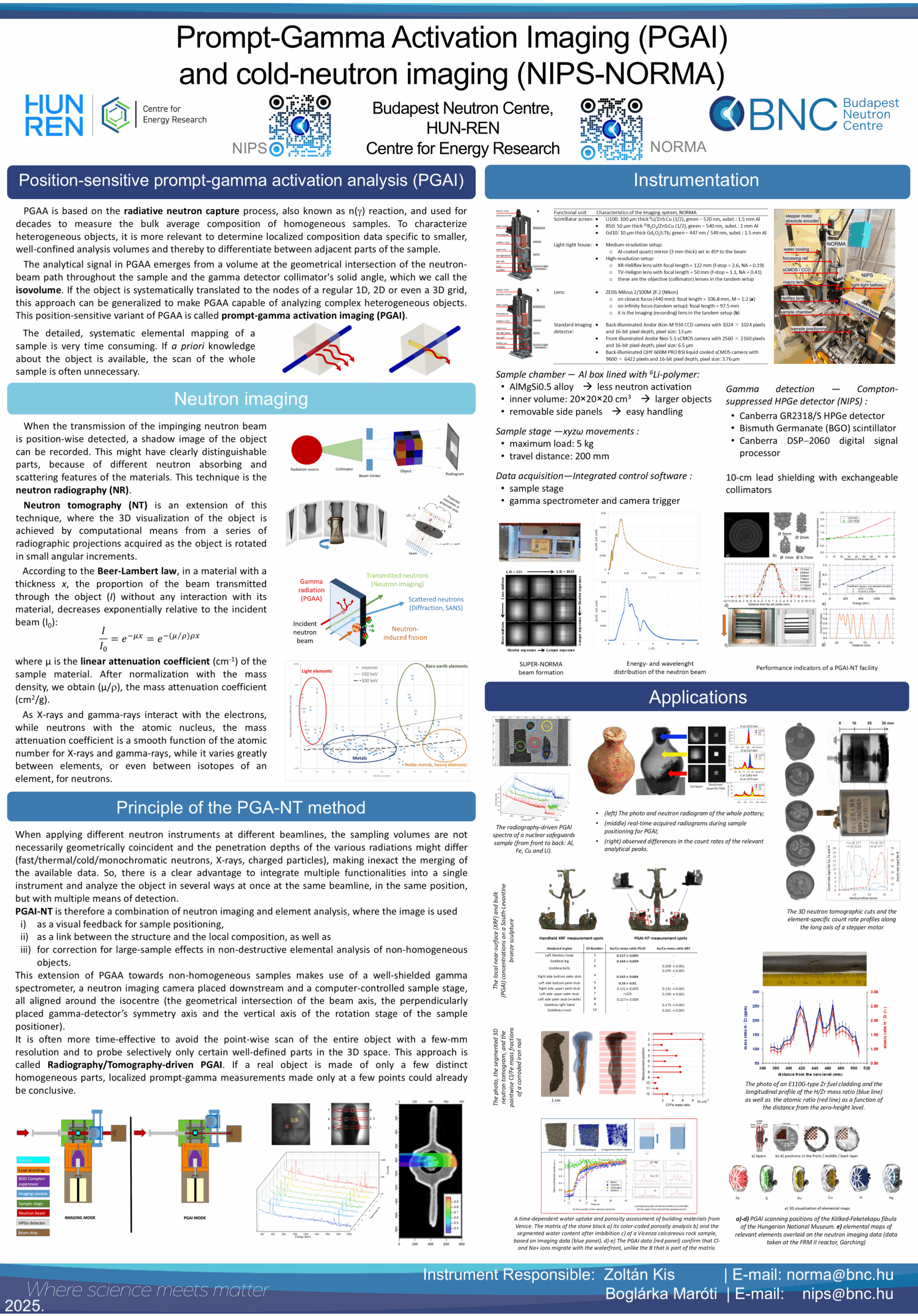
When the neutron beam passes through the material, its intensity decreases, and the attenuated beam creates a contrast pattern, i.e., a projected image on a sensitive screen. The NORMA station is one of the complementary parts of the NIPS-NORMA facility (Fig. 1). It has been designed for neutron radiography (NR) and tomography (NT), and as position feedback for imaging-driven Prompt Gamma Activation Imaging (PGAI). Objects are positioned in a sample chamber, where the beam’s size can continuously be adjusted up to its maximum of 40×40 mm2. The image detection of the NORMA station relies on digital imaging equipment being able to carry out 2D and 3D imaging using suitable scintillation screens. The modular design provides three cameras with different pixel sizes and chip sizes, a fix focal length lens and three different types of scintillation screens to choose the most suitable setting for the application. The reachable spatial resolution is highly setup dependent with a best current value for on-screen resolution of 35 μm. Due to beam divergence the resolution becomes worse as the distance from the screen increases. Applying the pinhole exchanger, the distance from the screen where better resolution is reachable can be extended at the expense of exposure time. Exposure times range from a few hundredths of a second to a few times tens of a second. For the manipulation, reconstruction, and visualization of the 3D neutron datasets (i.e., the tomographic images), the latest Fiji-ImageJ, Octopus 8.9, and VGStudio MAX 3.2 and KipTool software packages are used. In PGAI mode, the image-guided combination of the element information obtained with the NIPS gamma spectroscopy detector makes it possible to assign element analysis results to a well-defined volume of a large object.
The NORMA facility is located at the end position of the neutron guide No. 10/1 as a complementary part of the NIPS-NORMA facility. It has been designed for neutron radiography (NR) and tomography (NT), and as position feedback for imaging-driven Prompt Gamma Activation Imaging (PGAI). In this latter mode, the combination with the element information obtained with the NIPS gamma spectroscopy detector makes it possible to assign element analysis results to a well-defined volume of a large object.
The neutrons are guided from the cold neutron source of the Budapest Research Reactor to the experimental positions by a neutron guide, which is slightly curved to decrease the background coming from the reactor core. Before the main beam enters the experimental area, it is divided into two sub-beams (upper and lower) by suitable beam limiters, and the lower beam serves the NIPS-NORMA facility. The neutron guide features 2Qc supermirror guides that improved the thermal-equivalent neutron flux at the NIPS sample positions to 2.7×107 cm–2 s–1. The beam can be collimated to a maximum cross-section of 4×4 cm2. The intensity of the incoming neutrons is monitored and recorded with an ORDELA Model 4511 N neutron detector throughout the whole reactor campaign.
The beam arrives through a flight tube of 45×45 mm2 cross-section into a sample chamber with dimensions of 200×200×200 mm3 for imaging and position-sensitive applications. The frame of the chamber is made of AlMgSi alloy and lined from inside with 6Li-enriched polymer. By removing one or more side panels, larger objects (or at least parts of those) of up to 5 kg weight could also be imaged (such as a sword, vase, stone, etc.). Samples can be loaded manually from the top or placed onto an XYZω motorized sample stage with a travel distance of 200 mm and a guaranteed precision of 15 μm. The sample stage is introduced to the sample chamber from the bottom.
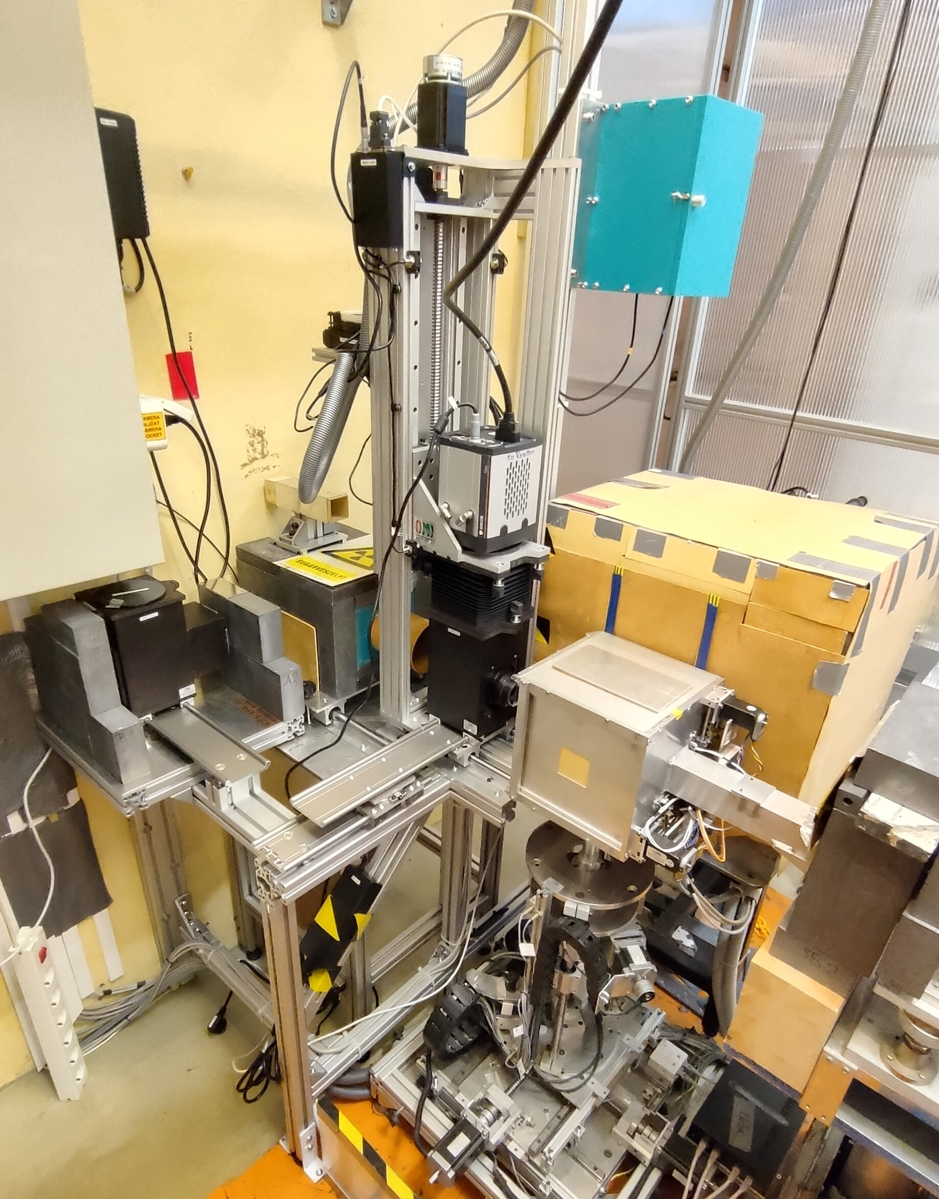
The experimental area is a 3×6.5 m2 room at the rear end of the guide hall (Fig. 2). The neutrons enter the cabin and fly along a long aluminum flight tube across the experimental area, to the beam stop placed at the wall of the guide hall. A pneumatically actuated instrument shutter is used to control the entry of the neutron beam into the cabin while two computer-controlled secondary shutters are in place to allow independent operation of the PGAA and NIPS-NORMA facilities.
The imaging system of the NORMA setup has a modular design. The various scintillator screens (LiF/ZnS:Cu, 10B2O3-based, Gadox P43) can be mounted either on a light-tight mirror house or on a house with infinity corrected tandem optics. The mirror house setup has a larger field of view with lower spatial resolution, in contrast to the tandem setup, which is highly effective in light collection but with smaller field of view. There is a macro lens with a fix focal length and high f-stop value (100 mm with f/2) available. There are three different cameras available, two sCMOS (Andor Neo 5.5, QHY600M PRO) and one CCD (Andor iKon-M). The focusing of the imaging system is carried out by moving both the camera and lens modules using stepper motors driven by an absolute encoder. The best optical magnifications are 0.5 and 0.8 for the mirror house and the tandem system, respectively.
The spatial resolution of the imaging system depends on both the actual modular setup and the object-to-screen distance. The best value for on-screen resolution is 35 μm when using the 10 µm thick Gadox P43 screen mounted on the tandem optics house, which is coupled to Andor Neo or the QHY600M PRO camera using the Zeiss Milvus 100 mm lens. A motorized pinhole exchanger and a graphite scatterer (SuperNORMA) are installed at the end of the neutron guide, which can adjust the L/D ratio, a measure of the neutron beam’s divergence, and at the same time making the beam spot more homogeneous (Fig. 3). The pinhole system is fabricated from a Li-6 enriched poly sheet with a neutron attenuation factor of at least 1000. It has three positions with aperture sizes of 550 mm2 (25×22 mm2, the original), 121.54 mm2 (Ø12.44 mm), 9.95 mm2 (Ø3.54 mm). There are two graphite scatterers with 2 mm and 3 mm thicknesses placed upstream, which could be positioned independently of the pinholes. The L/D ratio of the beam (Fig. 4) is now adjustable as 233 (550 mm2), 500 (121.54 mm2), or 1832 (9.95 mm2). It means that the distance from the screen where the spatial resolution is mostly affected only by the inherent resolution of the scintillation screen could be extended from 20 mm to about 100 mm, as demonstrated in Fig. 4. The advantage of the extended range of better spatial resolution plays an important role in the tomography of larger objects. The more uniformly irradiated field of view helps in normalizing the images properly, at the price of somewhat longer exposure times.
Beam size for imaging:
Beam cross-section for PGAA/PGAI:
up to 40×40 mm2
continuously adjustable rectangular slit
Collimation ratio (L/D):
Beam energy distribution:
233, 500, 1832
Cold beam
Scintillator screen:
- 100 µm thick 6Li/ZnS:Cu (1/2): green
- 50 µm thick 10B2O3/ZnS:Cu (1/2): green
- 10 µm thick Gd2O2S:Tb: green (Gadox P43)
Light-tight house:
- Medium resolution setup:
- Al coated quartz mirror set in 45º to the beam
- High-resolution setup:
- XR-Heliflex lens with focal length = 122 mm (f‑stop = 2.6)
- it is the objective lens in the tandem setup
Lens:
- ZEISS Milvus 2/100M ZF.2 (Nikon)
- at closest focus (440 mm): focal length = 106.8 mm, M = 1:2
- at infinity focus (tandem setup): focal length = 97.5 mm
- it is the imaging lens in the tandem setup, M = 1:1.25
Standard imaging detector:
- Back-illuminated Andor iKon-M 934 CCD camera with 1024×1024 pixels and 16-bit pixel depth
- Front-illuminated Andor Neo 5.5 sCMOS camera with 2560×2160 pixels and 16-bit pixel depth
- Back-illuminated QHY600M PRO BSI liquid cooled sCMOS camera with 9600×6422 pixels and 16-bit pixel depth
Spatial resolution (on-screen, examples):
- 35 μm (Gadox P43 + Heliflex122 + Milvus 100 + Neo)
- 35 μm (Gadox P43 + Heliflex122 + Milvus 100 + QHY)
- 50 μm (Gadox P43 + MirrorHouse + Milvus 100 + Neo)
- 80 μm (Gadox P43 + MirrorHouse + Milvus 100 + iKon)
- 120 μm (Li100 + MirrorHouse + Milvus 100 + Neo)
- 150 μm (Li100 + MirrorHouse + Milvus 100 + iKon)
Sample stage:
xyzω motorized sample stage with a travel distance of 200 mm and a guaranteed precision of 15 μm
Sample chamber dimensions:
200×200×200 mm3
Sample environment:
Ambient room pressure and temperature
Thermal-equivalent flux at target:
2.7×10⁷ n cm-2s-1
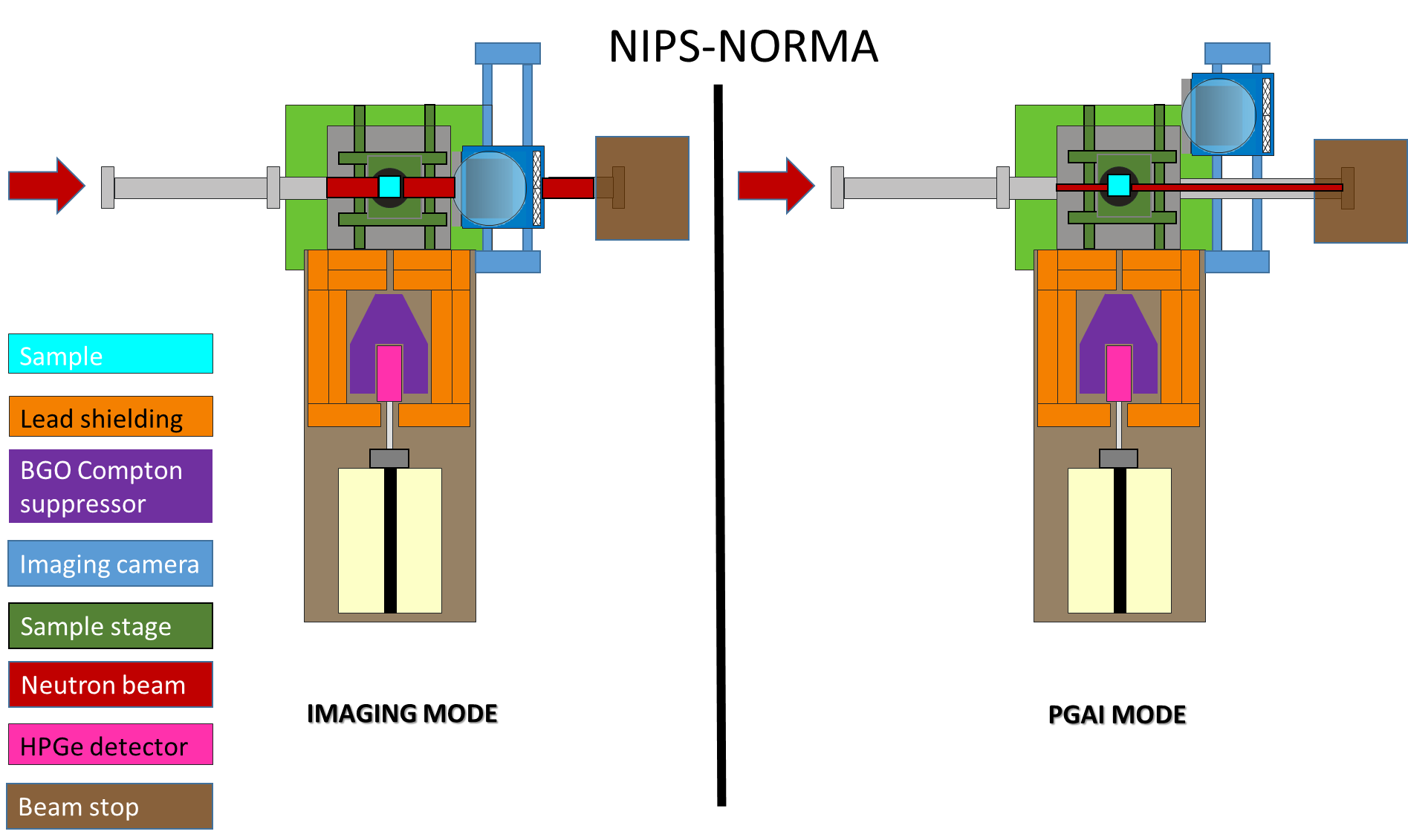
Fig 1. Operation modes of the NIPS-NORMA station
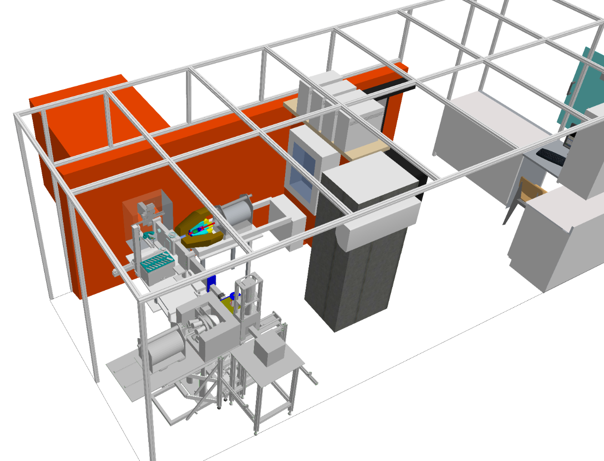
Fig. 2. Overview of the PGAA NIPS-NORMA cabin
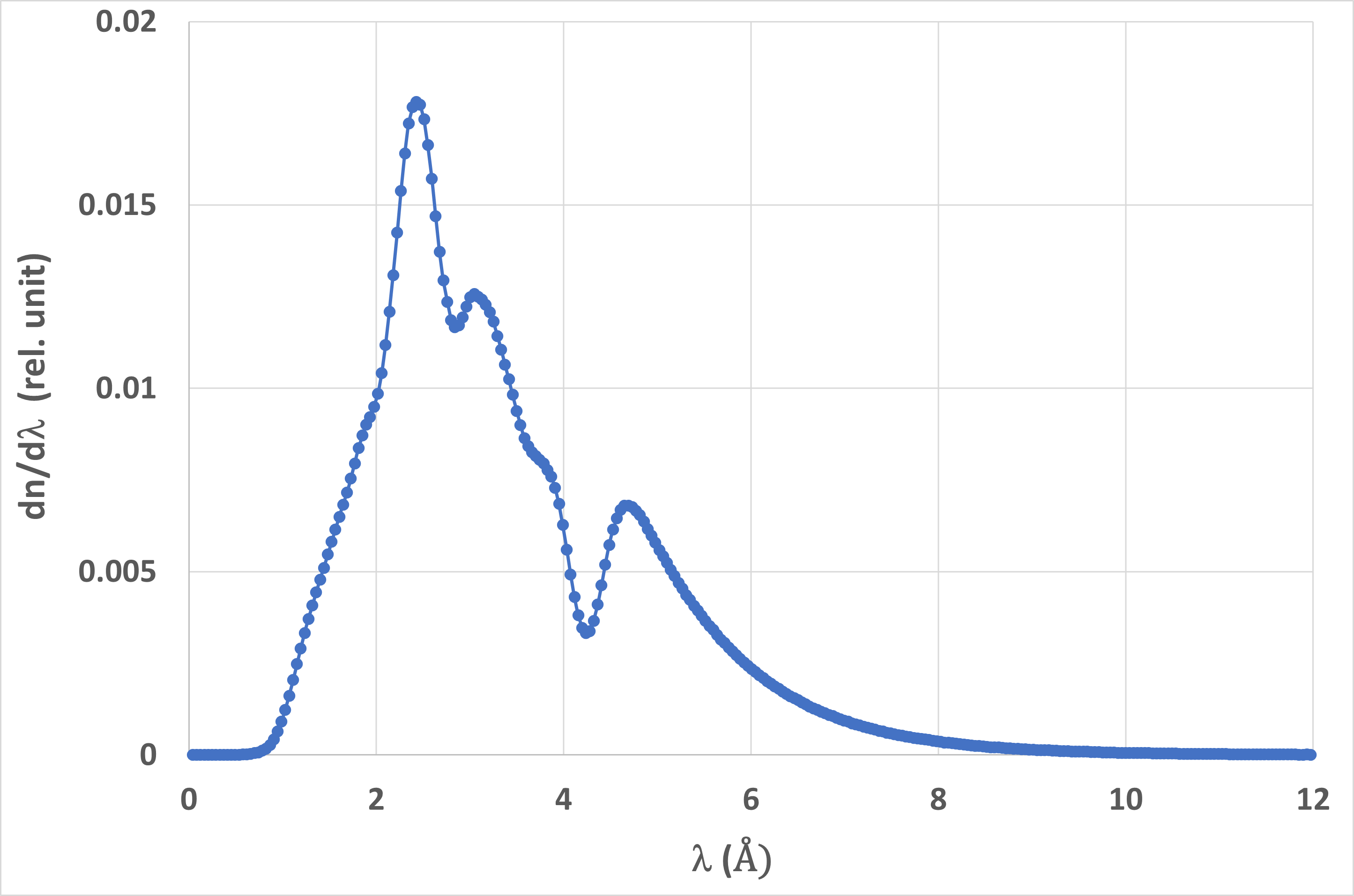
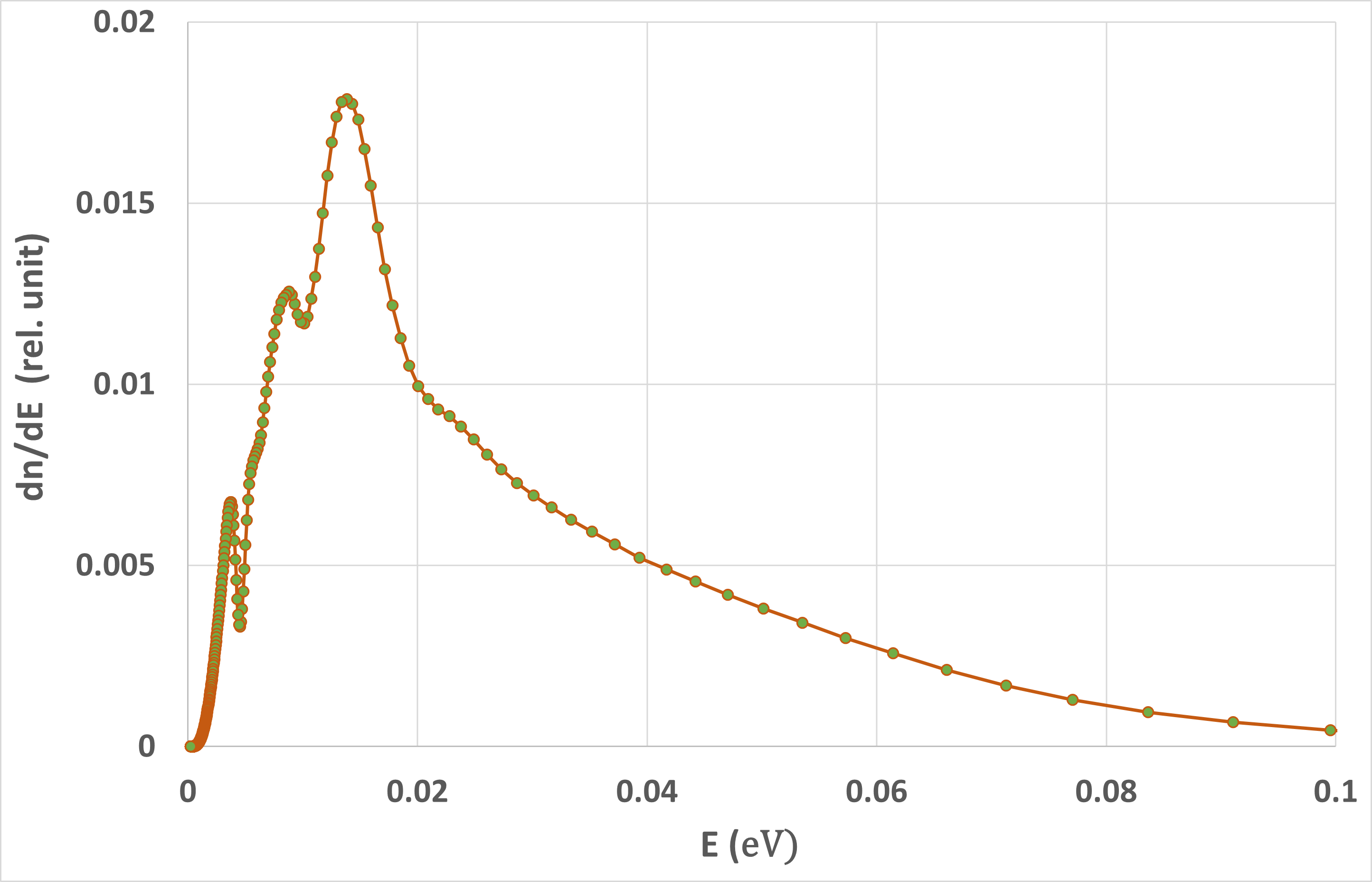

Fig 3. (left) The wavelength and the energy-dependence of the neutron beam. (right) The neutron beam intensity at the sample position of the NIPS-NORMA facility, with and without the graphite scatterer inserted at the end of the neutron guide.

Article about the instrument in more detail:
Zoltán Kis; The redesigned neutron imaging facility, NORMA at BNC, Budapest. Rev. Sci. Instrum. 1 July 2024; 95 (7): 073702. https://doi.org/10.1063/5.0208844